I/O-Modules
Fox Series
MDI-8, Digital Input
Sub-module
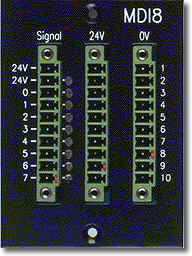
The MDI-8 input module is a submodule for the CNX21 base module, which is galvanically decoupled by means of optocouplers that provides eight digital inputs. For operation in the II/O system, you can install up to three MDI-8s in the four slots of a CNX21 base module. This makes possible a maximum of 24 inputs per CNX21. In addition, you can combine digital MDI-8 input modules with different modules, e.g. digital outputs.
|
Technical data |
MDI-8 |
|
Inputs |
8
inputs, galvanically decoupled 8 LED status indicators 1 LED voltage indicator |
|
Input Level |
Supply
voltage: 10V .. 32 V Supply voltage standard: 24V -Level. Switching threshold is always half the supply voltage. Input resistance: 15 Kohm Input current at 24 V: < 2 mA |
|
Input Decoupling |
Galvanically separated by optocoupler |
|
Input filter |
The
inputs are a) digitally filtered at 6 ms b) hardware-debounced at 3 ms |
|
Polarity Reversal Protection |
The inputs are protected against polarity reversal |
|
Supply Voltage |
24 VDC (± 20%) |
|
Current consumption |
0.05 A (without load and input currents) |
|
Housing |
Module with front panel is mounted in the CNX21 using two screws. |
|
Dimensions (WxHxD) |
58 * 72 * 50 mm |
|
Weight approx. |
100 g |
|
Operating temperature |
0°C ... +55°C |
|
Storage temperature |
-20°C ... +70°C |
Signal Description
|
Pin |
Signal |
I/O |
Description |
| L-1 | +
24V |
VCC |
+ 24
VDC output
driver supply |
| L-2 | +
24V |
VCC |
+ 24
VDC output
driver supply |
| L-3 | DI
0 |
In |
Bit
0 of data byte 0, 1, 2 or 3 |
| L-4 | DI 1 |
In | Bit 1 of data byte 0, 1, 2 or 3 |
| L-5 | DI
2 |
In | Bit
2 of data byte 0, 1, 2 or 3 |
| L-6 | DI 3 |
In | Bit 3 of data byte 0, 1, 2 or 3 |
| L-7 | DI
4 |
In | Bit
4 of data byte 0, 1, 2 or 3 |
| L-8 | DI 5 |
In | Bit 5 of data byte 0, 1, 2 or 3 |
| L-9 | DI
6 |
In | Bit
6 of data byte 0, 1, 2 or 3 |
| L-10 | DI 7 |
In | Bit 7 of data byte 0, 1, 2 or 3 |
| M-1 |
+
24V |
VCC |
+ 24
VDC supply for
feeding the sensors |
| M-2 | +
24V |
VCC |
|
| M-3 | +
24V |
VCC |
|
| M-4 | +
24V |
VCC |
|
| M-5 | +
24V |
VCC |
|
| M-6 | +
24V |
VCC |
|
| M-7 | +
24V |
VCC |
|
| M-8 | +
24V |
VCC |
|
| M-9 | +
24V |
VCC |
|
| M-1 |
+
24V |
VCC |
|
| R-1 | 0V |
GND |
ground, feedback of outputs |
| R-2 |
0V |
GND |
|
| R-3 | 0V |
GND |
|
| R-4 |
0V |
GND |
|
| R-5 | 0V |
GND |
|
| R-6 | 0V |
GND |
|
| R-7 | 0V |
GND |
|
| R-8 |
0V |
GND |
|
| R-9 | 0V |
GND |
|
| R-10 |
0V |
GND |
back | Fox Series | Download | Home
Copyright © 2000 TRS
Fieldbus Systems, Inc. All rights reserved.
Revised: July 13, 2000
.